Stirred tank is one the most widely used reactor in the Chemical and Process Industry. It is used to process single phase systems as well as multiphase systems ( gas-liquid, liquid-solid, gas-liquid solid).
Design Elements in Stirred tank
Any stirred tank has following main design elements
Tank Design: The cylindrical tank with top and bottom dish. Most of the top and bottom dish are either (1) Elliptical (2) Torispherical (3) Hemispherical or (4) Conical. The cylindrical tank have typical H/D ratio of more than 1. The Cylindrical Height, H, Tank Diameter (DT) and the dish height needs to be specified (or designed) to meet the production target
Impeller: Impellers are the heart of the Stirred Tank. Impeller selection and design are the most critical design elements. Impellers are selected to meet the process requirements. The selection is also guided by the viscosity of the fluid and the number and nature of the phases involved. Most commonly, Impellers are classified as (1) Axial (2) Radial and (3) Tangential flow impellers
Stirred tank
Internal Accessories: Tanks are commonly employed with four baffles of height equal to the maximum liquid height.
Another internal is a heating/cooling Coil. Depending on the heat transfer requirements, the dimensions of the coil are designed.
Performance Expectations from a Stirred tank
Our services
The existing units experience one or more of the following challenges. We can help to solve these problems
Lab scale batch time is 2 hours where as plant scale it is 24 hours
Inconsistent product purity, selectivity, yield over the two scales
Wide Crystal size distribution and too many fines
Segregation and/ settling of solids
Higher power consumption
Suboptimal heating or cooling time
Agglomeration/film formation in blending viscous liquids
At the design stage, we can help to ensure that the stirred tank does the job!
Evaluate Design Performance and optimization
Evaluate alternative technologies/designs
Analyse the complete process, optimize operating conditions,
Establish material and energy balance of the entire plant and
Identify/validate/quantify process improvement opportunities
Scale up
We help in your process intensification goals
Converting the Batch process to Continuous
Reactor sizing, providing appropriate number of reactors and configurations in series to yield appropriate residence time, distribution and mixing for reactions
Sequencing the operations
Evaluate the usage of current assets to be used for continuous plant
Design and Characterization of Micro reactors
Design Evaluation for given chemistry
Heat Transfer
Conversions
Our Methodology
Lorem ipsum dolor sit amet, consectetur adipiscing elit. Ut elit tellus, luctus nec ullamcorper mattis, pulvinar dapibus leo.
Equipment capability to produce desired production
Understand current performance from historical data
Unable to maintain steady required temperature
Analyse Power consumption ( Impeller Motor Amperage) trends
Are the solids setting/getting carried over?
Any possibility of short circuiting?
Understand the design, study design ratios, analyse impeller selection and speed
Calculate heat load, heat transfer surface provided, heat addition/removal rates
Suggest/carry out Expt to identify the effect of Stirrer speed, catalyst concentration, particle size, gas dispersion, bubble size, sparger design on mass transfer, reaction, heat transfer
Calculate Stirrer speed for effective heat transfer, gas dispersion, solid suspension, blending, mixing, optimal power consumption
Basic Impellers commonly used in the industry are Rushton Turbine impellers and Pitched blade impeller.
The electrical energy supplied by the motor is converted into kinetic energy. This results in generating the flow in the fluid and in generating the turbulence. Accordingly, the impellers are classified as
(A) Flow generating Impellers and (B) Turbulence generating Impellers.
Another approach used to classify the impellers is the way they generate the flow in the tank;
Based on the Impeller diameter with respect to the tank diameter, they are classified as
(A) Open Impellers (Impeller Diameter almost 0.5 times the tank diameter
(B) Closed Impellers (Impeller Diameter is almost equal to the tank diameter)
Flow Number (Nq) and Power Number (Np) are the main parameters that characterizes the Impeller. Higher the power number, higher is the power consumption.
For example, to carry out blending operation, a lot of shear is needed whereas for solid suspension, gas dispersion turbulence needs to be generated. the systems involving highly viscous fluids, impeller with diameter almost equal to the tank diameters are needed thereby imparting more torque at lower speed. Thus, depending upon the application, the impeller needs to be selected.
Thus, selecting right impeller is the key step. We have the experience and expertise to guide you in selecting the right impeller for the process.
Axial Flow Impellers (Open Impellers)
Axial flow impellers generate flow in the axial direction of the tank. High Efficiency Impellers ( Low Power Number) consume less power and are more popular. The pitched blade impeller is very commonly used as it is easy to fabricate. These impellers are used for efficient heat transfer, mixing, solid suspensions etc.
Radial Flow Impellers (Open Impellers)
Radial Impellers generate radial flow more dominantly. The standard Rushton Impeller is very common radial impeller as it generates high turbulence in the tank. These impellers are commonly used for effective liquid mixing, heat transfer, and gas dispersion.
Close Impellers (High Viscosity), Tangential Flow Impellers
Closed Impellers are the impeller whose diameter is very close to the tank diameter. A very common closed impeller is Anchor impeller and GATE impeller. These impellers generate tangential flow. Other examples of closed impeller are Ribbon, Ribbon with screw and double ribbon impellers. These impellers generate axial flow leading to axial mixing.
These impellers are used for mixing high viscosity fluids. They are good for the heat transfer applications as the impeller diameter is almost equal to the tank diameter
Impellers for Gas Dispersion
Radial flow impellers are used for gas dispersion. But as the power number for standard Rushton turbine is very high, variants like Anti Ragging, Smith turbine, Ekato Intermig are also used in Fermenters
Selecting Impeller Speed
Equally important is to determine the impeller speed. The impeller needs to operate at right speed to meet the objectives like blending, solid suspension, gas dispersion etc. Theoretical correlations are available to calculate minimum speed required for these operations.
Uniform solid suspension
Uniform dispersion of gases
Meet desirable heating/ cooling performance
Ensure proper Mixing Time
Achieve right Mass transfer rates
Optimal Power Consumption
Some general guidelines are available in terms of power consumption ( or power needed) to carry out the applications. e.g, Blending, 0.1 to 0.8 KW/ton of power needs to be supplied. They are summarized below
Once the tank is designed, impeller is selected and operating speed chosen, it is time to design the heating/cooling system. Jackets, limpet coil, internal coils are used for this purpose. Most effective is the limpet coil. We adopt following methodology to calculate the surface area for heating so that the desired heating/cooling rate is achieved. The sizing process is done in a loop till optimal sizing is done
The first iteration of design is complete at this stage. However, this design is not optimal. we then change the H/D ratio, select another compatible impeller and repeat the whole process all over and arrive at the optimal design. This Optimal design has following features
Optimal H, D, Impeller Diameter
Optimal Impeller location, Speed
Effective Jacket Design/Coil Design
Optimal Power Consumption
Uniform Suspension, Temperature Uniformity,
Mixing time, gas holdup, interfacial area, mass transfer coefficient, conversion, yield
Minimal Operating Cost, Fixed Cost
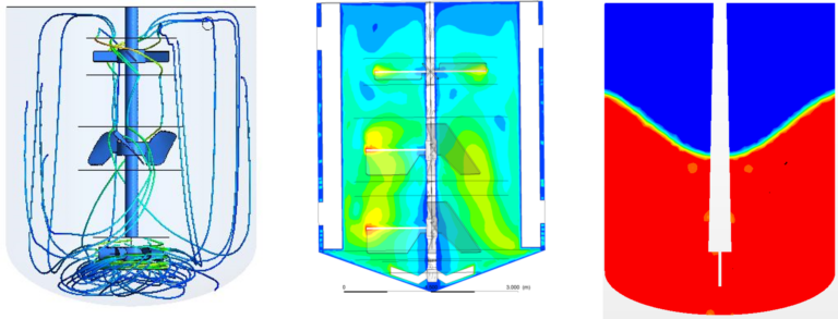
The above optimal design is based on experience, thumb rules and empirical correlations. Before delivering the design, we perform CFD Analysis of the tank with the impeller at the operating conditions. The following performance parameters are ensured and then the design is finalized
Mixing profiles, RTD, power consumption,
Desired gas dispersion, solid suspension, heat transfer, kla, extent of reaction,
Minimal short circuiting, dead zones
Temperature uniformity
Appropriate Impeller Selection, Sizing, optimal number of impellers, Impeller locations
Optimal sparger design
Optimal injection locations for better mixing
What can CFD do?
A full 3D, to the scale CFD analysis gives a detailed understanding of the hydrodynamics, heat and mass transfer, chemical reactions and thus the overall performance. CFD analysis would help us to ensure following design requirements are met.
Uniform Solid suspensions, gas dispersion
Expected Heat and mass transfer rates
Desired conversion and yield
Dispersed and stratified flows
Reactions within and between phases
Optimize impeller design
Optimize tank sizing
Impeller selection
Inputs needed for CFD Analysis
Design Information
General Assembly drawing of the tank indicating spargers, impellers, baffles, liquid level, any other internal in the tank
Detailed drawing of the impellers and sparger. Impeller detail would include blade dimensions, overall impeller diameter, disc diameter, number of blades, number of impellers, spacing between the impellers and bottom clearance
Sparger drawing details would include sparger pipe diameter, number of holes, their orientation on the pipe, location wrt to the impeller
Inlet /outlet locations
Process Information:
A short process description
Problem statement
Density, Viscosity of the process fluid
Inlet/outlet flow rates
Gas flow rate, gas density, viscosity
Solid loading (wt%), solid density, particle size (distribution) and shape,
Jacket/coil temperature, Process fluid initial temperature
Final Heating/cooling desired temperature.
Operating condition:
Impeller Speed
Finally! Complete Design
Once CFD Analysis has ensured that all the design requirements are met with minimal power consumption, at optimal operating and fixed costs, the final design drawing is prepared and submitted with all the design dimensions
Equipment capable to produce desired production
Able to maintain steady, uniform, and required temperature